A Revit material has two separate looks: the texture on its Appearance tab (what Realistic views and renders show) and the surface and cut patterns on its Graphics tab (what the other views draw). They only line up when four things agree: the pattern is a model pattern, the texture is positioned with Texture Alignment, the texture’s Sample Size equals the real size the image covers, and the image holds a whole number of pattern repeats. This page walks through the five fixes with Autodesk’s own steps, and marks where the sources disagree.
Why the texture and the pattern do not line up
Autodesk’s help says surface and cut patterns are the “graphic representation” of the material and that, to change how the material looks in rendered images, you change its render appearance. So the pattern lines and the picture are two separate objects with two separate sizes and two separate starting points. Nothing forces them to agree; you have to make them agree.
Surface pattern or cut pattern: which one matters here
Both live on the Graphics tab, each with a foreground and a background fill pattern and colour. The surface pattern is drawn on an element’s face; the cut pattern is drawn where the element is cut (sections and plans). Autodesk’s Texture Alignment steps start under Surface Pattern and align the texture to the surface pattern, so the surface pattern is the one that has to match the texture.
Which pattern type may each one use? Tested by the Motif team in Revit 2023: the Surface pattern accepts a model or a drafting fill pattern; the Cut pattern accepts a drafting fill pattern only. Setting a model pattern as the Cut pattern was refused by Revit with the message “The FillPattern target must be a drafting pattern”. Other sources, for context:
- An Autodesk video transcript says: “you will typically use drafting patterns for the cut, and model patterns for the surface.”
- cad-notes.com (2023-10-25) says only drafting patterns can be used for cut patterns, which is what the test found.
- A 2016 Autodesk Ideas post asks for “Model Pattern in Cut Pattern at a Costum Scale”, a request that fits the same limit.
So the usual setup is also the only one that works in Revit 2023: model for the surface (the one Texture Alignment needs), drafting for the cut. We did not run other Revit versions.
Fix 1: use a model pattern for the surface foreground
This is the most common cause and the first thing to check. Autodesk: “If the Texture Alignment button is not active, specify a model fill pattern for the material’s surface pattern. You cannot align a drafting fill pattern.”
Why the difference: Autodesk says a drafting pattern keeps its size and spacing whatever the view scale, while a model pattern is fixed to the model: its lines measure real distances, scale with the view, and can be moved, rotated and aligned to other elements. A forum reply to a user whose photo texture would not line up asked the same question: the pattern may be “a drafting pattern instead” of a model one (Align texture, 2017).
- Open Manage > Additional Settings > Fill Patterns. Under Pattern Type, Model and Drafting are listed separately.
- In the Material Browser, open the material’s Graphics tab, click the pattern under Surface Pattern > Foreground and pick a pattern that is a model pattern.
Fix 2: align the texture with the Texture Alignment tool, and align the pattern with Align
Two tools move two different things. Texture Alignment moves the image under the pattern; the Autodesk Community expert’s answer in a 2021 thread was that it “aligns the Appearance (image) relative to the surface pattern”. The Align tool on the Modify tab moves the pattern lines to element edges. A user who nudged the texture and saw nothing change was told “You are using the wrong feature” (thread).
Autodesk’s steps for Texture Alignment:
- In the Material Browser, select the material and open the Graphics tab.
- Under Surface Pattern, click Texture Alignment for Foreground. The dialog shows the texture with the surface pattern on top.
- Use the arrows to position the texture against the pattern lines, then click OK.
Autodesk adds two tips: rotating the texture or changing its sample size is done in the render appearance properties, not in this dialog, and a dark texture with black pattern lines may hide the lines, so switch the lines to a light colour while you align.
Fix 3: set the texture’s Sample Size to the real size the image covers
In the Appearance tab, open the image in the Texture Editor. Autodesk’s Sample Size field reads “Specify the size that the image represents.” Width and height are set there. If the image shows a single tile, the size is one tile; if the image shows eight tiles, it is eight tiles.
Arkance’s worked example: an acoustic ceiling tile of 600 mm whose sample image shows 8 tiles. Setting the sample size to 4800 made the texture reflect the real tile size; then Texture Alignment and its blue nudge buttons lined the image up with the hatch lines.
Fix 4: check units and scale
The same Arkance article found that the pattern lines were correct but the texture drifted: “a 2 foot US tile differs from a 600mm tile by a tiny amount that accumulates over long distances”. A texture sized for 2 ft and a pattern drawn for 600 mm are a different size on every tile, so the error grows across a floor.
- Use the same real-world tile size in the pattern and in the Sample Size, in the same unit.
- When you import a .pat, Revit’s Create a Custom Fill Pattern dialog has an optional Import scale field. If an imported pattern comes out the wrong size, check it first (our suggestion, not an Autodesk statement).
Fix 5: make the image match the pattern repeat, and make it seamless
Pattern and image have to repeat at the same distance. If the image holds a running-bond layout but the pattern is a stack bond, no setting will make them coincide. Autodesk Community advice on a plank-floor question (2018): find an image “that matches the hatch pattern (running bond)”, and it is best to use a “seamless” texture so the tiling does not show. In practice this is where most people stop: a photo cut from a brochure does not repeat cleanly, and cropping it so the joints sit exactly on a pattern repeat is manual work in an image editor.
Rule of thumb (our reading of the two sources above, not an Autodesk statement): the image must contain a whole number of pattern repeats, and the Sample Size must be that number times the repeat’s real size.
Motif for Revit: the texture and the patterns from one library pattern
This section is about our own add-in (3dshouse makes it). Motif is a Revit add-in for Windows. You pick a library pattern (herringbone, running bond, basketweave and more), set the sizes, joints and material, and press Create Revit material. It creates the material in the open project, or replaces one of the same name, with a seamless texture on the Appearance tab, a Surface pattern and a Cut pattern, all drawn from the same pattern. The Surface pattern is a model pattern, which is what Texture Alignment needs, and the Cut pattern is a drafting pattern, the only kind Revit 2023 accepted there. The texture’s real-world size is set from the pattern’s repeat, so there is no Sample Size to type.
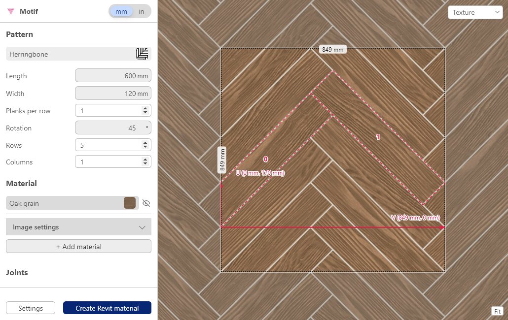
Check the result the way you would check any material: Material Browser > Graphics > Texture Alignment. Limits: Windows only; built for Revit 2021 to 2026, tested on Revit 2023; the add-in is not digitally signed yet, so Revit shows a “Security – Unsigned Add-In” dialog (choose Always Load); it needs an internet connection; 3 free uses per UTC day with a free 3dshouse account, asked for at the first use; one use is one material created or replaced. Details and install steps are on the Motif page.
Other routes to the same pieces: the web editor Texturic makes the seamless texture of a library pattern as an image, and Hatchy saves a library pattern as a .pat hatch file you load yourself (how it works).
Sources (all opened 2026-10-28)
- Autodesk help: Align the Render Appearance to the Surface Pattern
- Autodesk help: About Drafting Patterns and Model Patterns
- Autodesk help: About Fill Patterns
- Autodesk help: Change the Graphics Properties of a Material
- Autodesk help: Texture Editor
- Autodesk help: Video, Create a Fill Pattern (transcript)
- cad-notes.com: Understanding Surface and Cut Patterns in Revit (2023-10-25)
- Arkance: Aligning Revit Textures with Model Hatch pattern fill styles (updated 2025-02-13)
- Autodesk Community: Align texture (2017)
- Autodesk Community: Texture alignment, model type, new material (2021)
- Autodesk Community: texture mapping (2018)
- Autodesk Ideas: Cut Pattern in Materials (2016)
FAQ
Why is Texture Alignment greyed out in Revit?
Autodesk’s help says: “If the Texture Alignment button is not active, specify a model fill pattern for the material’s surface pattern.” and “You cannot align a drafting fill pattern.” (Align the Render Appearance to the Surface Pattern).
What is the difference between a surface pattern and a cut pattern in Revit?
Both are fill patterns on the material’s Graphics tab. Per Autodesk, fill patterns define “the surface patterns and cut patterns for the graphic representation of elements in the model” (About Fill Patterns). The surface pattern is what you see on an element’s face; the cut pattern is what you see where the element is cut in a section or plan.
Can a cut pattern be a model pattern?
Not in Revit 2023, as tested by the Motif team: the Cut pattern of a material took a drafting fill pattern and Revit refused a model pattern with the message “The FillPattern target must be a drafting pattern”. The Surface pattern took either kind. A 2023 article says “only drafting patterns” can be used for cut patterns, and an Autodesk video transcript says you “will typically use drafting patterns for the cut, and model patterns for the surface”. See the section “Surface pattern or cut pattern” above.
Why does my pattern show in Shaded view but not in Realistic view?
Different tabs drive different views. A reply on an Autodesk forum thread (2023) says that in non-Realistic views only the Graphics tab shows, otherwise the Appearance information is used. Autodesk’s help adds: “To change the appearance of a material in rendered images, change its render appearance.” (Change the Graphics Properties of a Material).
How do I make a drafting pattern a model pattern?
In Revit’s Fill Patterns dialog you choose Drafting or Model under Pattern Type when you create a pattern (Create a Custom Fill Pattern). A 2019 forum thread describes the file-side route: adding the line ;%TYPE=MODEL to the .pat file, which the poster calls clunky and says gave scaling issues (Model Patterns).
Why does my brick pattern disappear when I zoom out or print at 1:200?
Autodesk explains pattern overscaling: when you zoom out far enough, a pattern becomes denser and eventually displays as a solid fill (About Drafting Patterns and Model Patterns). A forum reply to the same symptom: “The pattern it too dense to show.” (Revit surface pattern textures).
Does the surface pattern change how the material looks in a render?
Autodesk says the opposite is the case: to change the appearance of a material in rendered images, you change its render appearance. The surface and cut patterns are the graphic representation in the views that use the Graphics tab.
Free: limited to 3 uses a day
Pro: unlimited, guaranteed to work, priority support