Tiếng Việt
SketchUp
CNC & Laser Cutting Panels SketchUp — 30 Dynamic Models
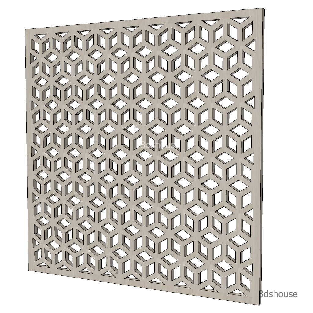
Designing CNC and laser cut flat panels directly inside SketchUp is one of the most time-efficient workflows available to interior designers and fabricators working with decorative partitions, screens, and wall panels. Instead of drawing a 2D layout in AutoCAD, re-importing it into SketchUp for visualization, then exporting back to DXF, the entire pipeline — parametric panel design, custom shaping, and cut-ready DXF export — runs inside a single SketchUp session using Dynamic Components and the ABF flat-pack export plugin. The Parashape library on 3dshouse.com provides ready-made Dynamic Component panels whose width, height, thickness, border width, pattern detail size, and pattern spacing are all adjustable through SketchUp’s Component Options dialog. Each parameter change re-tiles the pattern instantly — no manual redraw needed. When the dimensions are finalized, the ABF plugin reads the flat faces of the panel, nests them onto virtual sheet stock, and exports a DXF that goes straight to the laser cutter or CNC router operator. This article explains every step in detail, including the non-obvious constraints and workflow traps that trip up first-time users.
Key Features
- Fully parametric panel sizing. Each panel exposes width, height, and thickness as numeric inputs in Component Options. Changing width or height re-tiles the internal pattern to fill the new area automatically. There is no need to redraw motifs or manually space copies — the Dynamic Component engine handles the repeat math. This makes iterating through different client room sizes a matter of seconds rather than hours.
- Pattern detail stays at absolute size while tiling re-scales. The critical behavior is that the motif cell — the individual floral, geometric, or lattice unit — does not stretch when you resize the overall panel. Instead, the number of repeats adjusts. This means the cut detail remains at the same physical size across all your projects, which matters for structural integrity when cutting thin MDF or acrylic. The tradeoff is that the panel width and height should be whole multiples of the pattern’s spacing; if they are not, the last row or column clips, producing a partial motif at the edge.
- Adjustable border frame width. A separate border parameter controls the width of the solid frame around the perimeter. Increasing the border gives the panel more structural rigidity at the edges and is important when cutting large panels from thin material. The border geometry is also Dynamic-governed, so it scales in sync with the overall dimensions and does not require manual adjustment.
- Hidden geometry shows the structural mesh. Activating View → Hidden Geometry reveals the construction lines that form the repeat grid. These lines are not exported to DXF — they exist only as Dynamic Component references — but they are essential for diagnosing clipping at edges and for manually drawing custom shapes that align with the existing grid when you need a non-rectangular panel outline.
- Clean Dynamic for free-form custom shapes. The “Clean Dynamic” button strips all parametric attributes from the component, converting it to ordinary SketchUp geometry. This is required before cutting the panel to a non-rectangular outline (arch, angled corner, circular). After cleaning, you draw the desired outline, copy the panel face, intersect with the outline, and erase the excess faces and edges. Clean Dynamic is irreversible — the parametric attributes cannot be restored — so final dimensions must be locked before this step. For a custom outline that exists only as a logo or flat graphic (PNG/JPG) rather than drawn by hand, trace it into SketchUp faces first with Tracepen (installs from the Extension Warehouse).
- ABF plugin integration for cut-ready DXF export. The ABF plugin reads flat SketchUp faces and writes nested DXF layouts sized to your sheet stock. It eliminates the manual routine of copying faces to the origin, aligning them flat, then exporting one by one. For laser cutter operators who need all parts on a single A0 or 1220 × 2440 mm sheet, ABF’s nesting step alone saves substantial setup time. The DXF it outputs is 2D polyline geometry compatible with LaserCAD, RDWorks, Mach3, and most other CAM controllers.
How to Install and Use
- Install the Parashape plugin for 3dshouse.com. Download the .rbz file from the Parashape product page. In SketchUp, open Window → Extension Manager → Install Extension, select the .rbz, and confirm. SketchUp will add the Parashape panel library to your Extensions menu. No restart is required. Log in with your 3dshouse account when prompted — the free tier gives full access to the plugin interface; Pro unlocks the full model library.
- Browse and place a CNC panel model. Open Extensions → Parashape. The panel library is organized by motif style — geometric lattice, floral, arabesque, and others. Click a thumbnail to preview, then click Insert to place the Dynamic Component into your scene. The panel drops in at a default size (typically 1000 × 1000 mm). It is placed as a component instance, so every copy you place shares the same definition until you edit it.
- Set dimensions in Component Options. With the panel selected, open Window → Component Options. You will see numeric fields for Width, Height, Thickness, Border Width, Pattern Width, Pattern Height, and Pattern Spacing. Type your target dimensions directly. SketchUp redraws the panel immediately. For a room divider that is 2400 mm tall and 600 mm wide with 50 mm pattern cells and 80 mm spacing, set those values and the panel tiles automatically. If the last row clips, adjust the overall height by small increments until the edge motif closes cleanly — typically within ± 5 mm.
- Cut to a custom shape (optional). If the panel needs a non-rectangular outline — an arched top, mitered corner, or cutout for a socket — first confirm your final dimensions in Component Options, then click the Clean Dynamic button inside the component’s context menu or via the Extensions menu. After cleaning, explode the component (right-click → Explode). Draw the target outline as a flat face on top of the panel face. Use Edit → Intersect Faces → With Model to project the outline onto the panel pattern, then erase the faces and edges outside the desired boundary. Push/Pull the resulting face to the correct thickness and group it.
- Install the ABF plugin. ABF is a free SketchUp extension available on the Extension Warehouse. Search for “ABF” or “flat cut layout” and install it. ABF adds a toolbar and an Extensions → ABF menu. It requires SketchUp Pro because it calls SketchUp’s built-in DXF exporter — the DXF export API is not available in the free web version or the discontinued Make edition.
- Run ABF to nest and export DXF. Select all panel groups or components you want to export. Open Extensions → ABF → Export Cut Layout. Set your sheet size to match your raw material (e.g., 1220 × 2440 mm for a standard MDF sheet). ABF reads the flat face dimensions from each selected object, nests them with a configurable kerf gap and margin, and generates a 2D DXF file. Save the DXF and send it directly to your laser cutter or CNC operator. The output uses 2D polyline entities on a single layer, which is the format most CAM software expects.
- Verify the DXF before sending to the machine. Open the exported DXF in a free viewer such as eDrawings, LibreCAD, or DraftSight. Check that all outlines are closed polylines (open paths cause the laser to cut partial shapes), that the kerf gap between nested parts is at least 5–8 mm for MDF or 3–4 mm for acrylic, and that the sheet margin is at least 10 mm on all sides. If ABF produces open paths, the source geometry in SketchUp has gaps or T-intersections — go back and use View → Hidden Geometry to find and close them before re-exporting.
Pro Tips
- Lock dimensions before Clean Dynamic — always. Once you strip the Dynamic attributes, the panel is ordinary SketchUp geometry. If the client changes the room size, you cannot simply type a new width — you must either keep an unedited Dynamic copy on a separate tag/layer, or re-insert from the Parashape library and redo the custom shaping. The professional workflow is: place the Dynamic component, set dimensions, duplicate it to a “master” tag that is hidden and locked, then clean and shape a working copy. Every revision starts from the master copy, not from re-downloading the model.
- Align panel dimensions to the pattern grid before committing. Before you finalize dimensions, calculate the nearest clean multiple. If the pattern spacing is 80 mm and the border is 40 mm on each side, the available interior width is (total width − 80 mm). An interior width of 880 mm accommodates exactly 11 × 80 mm cells. An interior of 900 mm leaves a 20 mm remnant cell at the edge. Run this arithmetic for both width and height before you lock the dimensions. A small spreadsheet or even a calculator note saves significant rework downstream.
- Use component instances, not exploded copies, for multi-panel rooms. If your design uses the same panel type in 20 locations, keep them as instances of the same Dynamic Component definition. You can resize each instance independently through Component Options without affecting the others. If you explode and flatten all 20 panels, every future design change must be applied manually to each one. Keeping instances also keeps your file size small — the geometry is stored once, not 20 times.
- Set kerf compensation in ABF, not in SketchUp. Laser cutters and CNC routers remove material equal to the kerf width (typically 0.2–0.5 mm for a laser, 3–8 mm for a router bit). Do not shrink your SketchUp geometry to compensate — your 3D visualization will no longer match the drawing. Instead, set the kerf offset inside ABF’s export settings. ABF insets the polyline outlines by half the kerf value, so the cut centerline is on the correct boundary and the finished part comes out at the drawn dimension.
- Group each panel by material before exporting. If your design uses 18 mm MDF for structural panels and 6 mm acrylic for decorative inserts, nest each material separately in ABF with the correct sheet size and material thickness as the filename tag. Mixing materials in one DXF sheet causes confusion at the machine — the operator has to manually separate cuts, which introduces errors. Organize SketchUp groups with a consistent naming convention: “MDF-18-PanelA”, “ACR-6-InsertB”, and so on, so ABF’s part list reflects the material directly.
System Requirements
- SketchUp version: SketchUp Pro 2022 or newer required (Dynamic Components engine + DXF export API). SketchUp Go and SketchUp Studio subscriptions also qualify. The free SketchUp for Web and the discontinued SketchUp Make do not support DXF export and cannot run the ABF plugin’s export step.
- Operating system: Windows 10/11 (64-bit) or macOS 12 Monterey and newer. Both the Parashape plugin and ABF are cross-platform.
- Account: A free 3dshouse.com account is required to access the Parashape library. The full model library including premium CNC panel models requires a Parashape Pro subscription.
- ABF plugin: Free from the SketchUp Extension Warehouse. Requires SketchUp Pro for DXF export functionality.